Advanced Features for Tackling Complex Solidworks Assembly Assignments
- Patterns for components:
- Mate Citations:
- Clever fasteners
- Design and Configuration Tables:
- Seasoned mates:
- Detection of Interference:
- Animation and expanded views:
- Motion analysis and simulation:
- Conclusion
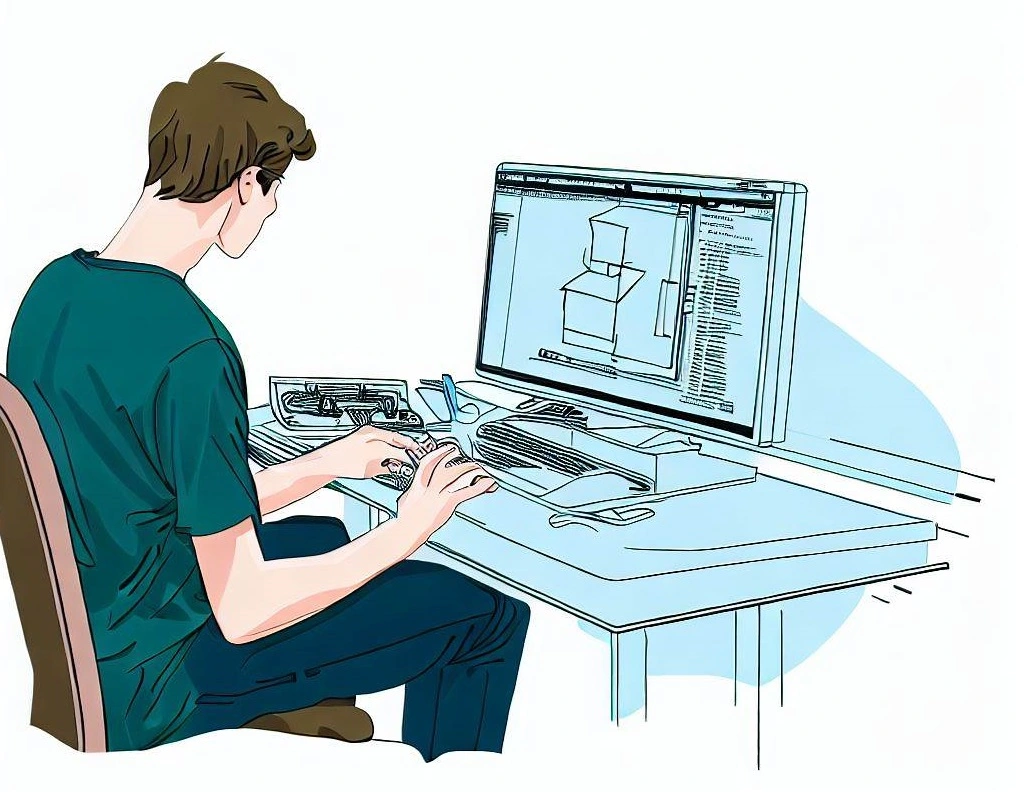
For the purpose of building intricate 3D models and assemblies, Solidworks is a top computer-aided design (CAD) program that is employed by numerous industries. Solidworks provides engineers and designers with a strong platform to execute their ideas thanks to its extensive set of tools and features. Solidworks offers a variety of cutting-edge features for solving complex assembly assignments that can significantly increase productivity and efficiency.
This blog post will discuss the advanced Solidworks features that are created specifically to handle challenging assembly tasks. We'll delve deeply into the capabilities of exploded views, simulation, mate references, advanced mates, configurations, smart fasteners, interference detection, and component patterns. Designers and engineers can fully utilize Solidworks' capabilities and reach new heights of design sophistication by grasping the subtleties of these features.
Component patterns enable effective component duplication within an assembly, resulting in significant time and labor savings. Mate references make mating easier while ensuring precise alignment and minimizing errors. Smart fasteners automate fastener placement, ensuring proper alignment and reducing labor-intensive manual labor. Multiple variations can be managed within a single file thanks to configurations and design tables, making customization and design flexibility simple. Advanced mates offer precise alignment options, supporting intricate assembly configurations. In order to ensure error-free designs, interference detection helps to identify conflicts and overlaps. Exploded views and animation improve comprehension and design reviews by helping to visualize and communicate the assembly process. Finally, performance can be assessed and functionality can be verified using simulation and motion analysis.
Designers and engineers can broaden their skill sets, improve workflows, and confidently create complex assemblies by investigating Solidworks' advanced features.
Patterns for components:
The component patterns feature in Solidworks gives users a wide range of options for replicating components within an assembly. It offers extensive customization options in addition to the ability to duplicate components. You have complete control over the placement, inclination, and orientation of the replicated components when using component patterns. The pattern arrangement and the number of instances can both be precisely specified. There are many different pattern types available in Solidworks, including linear, circular, and sketch-driven patterns. Circular patterns are useful for building radial arrays, whereas linear patterns are frequently used when replicating components along a straight path. By enabling you to specify a specific sketch as a pattern path, sketch-driven patterns give you even more control over component replication.
Designers and engineers can significantly reduce the time and work required to create assemblies with repeating elements by utilizing component patterns. When working with assemblies that require the repeated placement of parts like fasteners, bolts, or rivets, this feature is especially helpful. Component patterns allow for quick and effective duplication as opposed to manually placing each individual component. Associative patterns are also available in Solidworks, which means that any modifications made to the original component will be automatically propagated to the pattern instances. As a result, there is no longer a need for manual updates, ensuring consistency throughout the assembly and further boosting productivity and design accuracy.
Mate Citations:
As anchor points for components, mate references allow for precise and dependable alignment within an assembly. You create a consistent mating scheme that makes assembly easier and ensures precise component alignment by defining mate references on specific locations of a component. You can define mate references in Solidworks for a variety of features, such as holes, edges, or even specially made reference geometry. Due to this adaptability, designers are free to choose mating arrangements based on particular design requirements.
Mate references are essential for streamlining the assembly process, especially when dealing with intricate assemblies that demand exact alignment. You can automate the mating process and lower the possibility of mistakes or misalignments by defining mate references. Based on the specified mate references, Solidworks automatically detects and applies the proper mates when mating components. This ensures constant alignment throughout the assembly and significantly speeds up the process.
Because component sizes or configurations can vary in parametric assemblies, the use of mate references becomes even more beneficial. Designers can create intelligent mating relationships that adapt to changes in component sizes or configurations by using mate references. By doing this, the assembly is guaranteed to maintain proper alignment despite variations in component dimensions. In Solidworks, mate references offer a strong and effective method for achieving precise and adaptable assembly alignment.
Clever fasteners
The addition of fasteners to an assembly is revolutionized by Solidworks' Smart Fasteners feature. By intelligently detecting holes and assigning the proper fasteners based on predefined rules and configurations, it streamlines and automates the placement of screws, bolts, nuts, washers, and other fasteners. Designers no longer have to manually position each fastener or use time-consuming copy-paste procedures thanks to Smart Fasteners.
Solidworks keeps an extensive library of standard fasteners that come in a variety of sizes, types, and specifications when using Smart Fasteners. To meet particular standards or requirements for the industry, this library is easily expandable and customizable. Based on the established rules and configurations, Solidworks' intelligent system automatically detects holes in components and applies the appropriate fasteners. The system also takes into account selection of washers, head type, length, and thread size.
Smart Fasteners have many advantages, such as increased productivity, accuracy, and design coherence. Designers can drastically reduce the time and labor needed to populate an assembly with fasteners by automating the fastener placement process. The system makes sure that fasteners are properly sized, aligned, and chosen, minimizing the possibility of human error. When working with large assemblies or assemblies that call for a lot of fasteners, this feature is especially helpful. Designers can improve productivity, streamline the assembly process, and protect the design integrity by using Smart Fasteners.
Design and Configuration Tables:
In Solidworks, powerful tools like configurations and design tables make it easier to manage various iterations of an assembly within a single file. With configurations, designers can alter parameters, suppress or enable features, alter component sizes or options, and create various versions or states of an assembly. With this capability, it is possible to explore different design options without having to create separate files for each variation.
An effective tabular interface for managing and controlling these configurations is provided by design tables. They allow designers to enter particular parameter values for each configuration and provide a consolidated view of the various assembly states. By making switching between variations easier, design tables let designers quickly change or update dimensions, materials, or other design characteristics across various configurations. They provide a dynamic method of managing design options, which makes it simpler to alter the assembly to satisfy various client demands or design scenarios.
When working with product families or assemblies that have numerous options or variants, configurations and design tables are especially helpful. Designers can maintain a single master model with various configurations rather than creating separate files for each variation, saving time and effort in file management. Additionally, designers have the ability to build clever connections between configurations that let changes made in one configuration spread to others. When managing multiple variations of an assembly, this capability ensures consistency and lowers the possibility of errors or inconsistencies.
Designers can speed up the design process, increase productivity, and maintain a flexible and reliable assembly model by utilizing configurations and design tables. This allows them to adapt to various design scenarios or client demands.
Seasoned mates:
Beyond the fundamental coincident and concentric mates, Solidworks provides a wide variety of mate types that enable designers to create more intricate and precise assembly arrangements. These more sophisticated mates give you more flexibility and control over how parts move and align within an assembly.
For instance, width mates let designers set a specific gap or clearance between two components. This type of mate makes sure that parts are lined up at a specific gap, enabling precise spacing and fitment within the assembly. When designing assemblies that need precise tolerances or when incorporating moving parts with precise clearance requirements, width mates are especially helpful.
The ability to design a specific motion trajectory or path for a component is made possible by path mates. Designers can simulate mechanisms, conveyors, or assembly lines by assigning a path mate, which controls a component's movement along a predetermined path. When designing assemblies with complex motion, like robotic arms or sliding mechanisms, this mate type is essential.
By enforcing symmetry among components, symmetry mates make it easier to build symmetrical assemblies. Designers can guarantee balanced designs and precise alignment between mirrored components with the help of this mate type. Symmetry mates make it easier to align components symmetrically, saving time and effort and guaranteeing the assembly's aesthetic and functional integrity.
To replicate the motion of cam and follower mechanisms, cam mates were created. With this mate type, designers can specify how one component moves based on the cam-like rotation of another component. Designers can analyze the interaction and movement of components, ensuring proper functionality and improving the assembly design by accurately simulating cam and follower mechanisms.
Designers can create intricate and precise assembly arrangements in Solidworks by utilizing these advanced mate types. The wider selection of mate options gives designers more control over alignment, motion, and clearance, enabling them to precisely and confidently create complex assemblies.
Detection of Interference:
Solidworks' crucial feature of interference detection identifies potential collisions or overlaps between components in an assembly. Complex assemblies made up of numerous parts that might overlap or intersect can cause interference or collision problems during the manufacturing or operational phases. The interference detection tool in Solidworks makes it easier to find and fix these interferences.
The entire assembly is thoroughly scanned by Solidworks' interference detection feature, which also analyzes the spatial relationships between components. It finds and highlights places where components cross or overlap, giving the designer visual feedback. This feedback enables designers to quickly spot and take care of any interferences that might jeopardize the assembly's functionality or ability to be manufactured.
Solidworks allows for interference detection on specific components or subassemblies in addition to the entire assembly. In order to save computational resources and streamline the analysis process, this selective approach enables designers to concentrate on particular areas of concern.
Designers can proactively find and fix interferences early in the design process by using interference detection. This reduces the possibility of expensive manufacturing mistakes, guarantees proper assembly fitment, and improves the product's overall quality. The ability to quickly and accurately spot interferences promotes design efficiency and eliminates the need for physical prototyping or rework.
A strong tool called interference detection aids in the optimization of intricate assemblies and enables designers to produce flawless designs, effective manufacturing procedures, and durable product performance.
Animation and expanded views:
Exploded views and animation are effective Solidworks tools for communicating design intent and helping to visualize the assembly process. Exploded views offer a clear and concise illustration of the component relationships or the assembly process.
Designers can easily create exploded views in Solidworks by simply dragging objects away from one another along predetermined vectors or directions. The exploded view's visual impact and clarity are further improved by the ability to customize it. Designers can alter the distance between components, add notes or labels to distinguish between different parts, or even use balloons to display a complete list of materials. Exploded views are frequently used in service manuals, assembly instructions, and other documents that call for a step-by-step breakdown of the assembly procedure.
By simulating the motion of components, animation elevates the visualization of assemblies to a new level. Designers can specify motion paths, component rotation angles, and even simulate mechanisms or moving parts thanks to Solidworks' animation features. Designers can demonstrate how parts move, rotate, or interact with one another within an assembly by creating dynamic visualizations.
Animation adds a realistic and interesting representation of the assembly's functionality, which is especially useful in presentations, design reviews, or marketing materials. It aids stakeholders in picturing the product in use, facilitating better understanding and decision-making. Additionally, animation can be a potent internal communication tool that helps cross-functional teams work well together and give insightful feedback on the functionality and design of the assembly.
Designers can improve collaboration, better communicate design intent to stakeholders, and improve communication of their assembly designs by utilizing exploded views and animation.
Motion analysis and simulation:
Designers can assess and validate the performance of their assemblies using Solidworks' sophisticated simulation and motion analysis tools. Analysis of the assembly's structural integrity under various loading conditions is possible through simulation. It aids in locating potential weak spots, stress concentrations, or deformation-prone regions that could have an impact on the assembly's functionality and dependability.
Designers can apply forces, pressures, or constraints to the assembly and watch how it responds using Solidworks' simulation features. Designers can make sure that their designs can withstand the anticipated forces and environmental conditions by simulating real-world scenarios, such as operating conditions or expected usage.
On the other hand, motion analysis focuses on analyzing how the parts move within the assembly. Designers can specify motion inputs like springs, motors, or gravity and assess how the assembly responds to clearance, interference, or range of motion.
Designers can identify potential collisions or interferences between components and improve the design for more streamlined operation by simulating the assembly's motion. Verifying the effectiveness and efficiency of mechanisms or moving parts within the assembly is also made easier with the help of motion analysis.
Solidworks' simulation and motion analysis tools give designers the power to enhance their creations, use less material, perform better, and lower the possibility of expensive failures during the manufacturing or operational phases. Designers can make informed decisions, improve the performance of the assembly, and guarantee the overall success of the product by validating the design through simulations.
As a result, Solidworks' sophisticated features for complex assembly assignments, such as component patterns, mate references, smart fasteners, configurations, advanced mates, interference detection, exploded views, animation, and simulation, give designers a complete set of tools to handle challenging assembly tasks. These features improve productivity and efficiency while also enabling designers to create assembly designs with precise alignment, functional integrity, and dependable performance.
Conclusion
Solidworks' advanced features for managing difficult assembly tasks give designers and engineers a wide range of tools to streamline their work processes and produce accurate and effective designs. Professionals can improve productivity, accuracy, and overall design quality by utilizing component patterns, mate references, smart fasteners, configurations, advanced mates, interference detection, exploded views, animation, and simulation.
Component patterns help ensure consistent geometry throughout the assembly by drastically reducing the time and work needed to duplicate components. Mate references make mating easier, allow for precise alignment, and lower assembly errors. Fastener placement is automated with the help of smart fasteners, resulting in precise alignment and a significant reduction in design time. A flexible and effective method of managing variations within a single file is provided by configurations and design tables, which encourages design customization and uniformity.
Designers can create complex assembly arrangements with precise component relationships thanks to Solidworks' advanced mate options. In order to ensure error-free designs and avoid expensive manufacturing problems, interference detection helps locate and resolve conflicts or overlaps. By providing a visual breakdown of the assembly process and showcasing the functionality of moving components, exploded views and animation improve communication. Simulation and motion analysis make it possible to assess the assembly's performance and behavior, optimize design decisions, and confirm functionality.
By utilizing these cutting-edge features, designers and engineers can confidently take on challenging assembly tasks, enhance collaboration, and produce high-quality designs. Solidworks gives experts the ability to efficiently build complex assemblies, cutting down on design iterations and quickening the pace of product development. Solidworks continues to be a top option for designers and engineers across a range of industries thanks to its extensive toolkit, which enables them to push the boundaries of innovation and design excellence.